Macro Pad Keyboard
Materials: PCB, Anodize Aluminum
Processes: CAD Design, CNC Machining, Anodizing, Soldering, Light Coding / Firmware Config.
Tools: Fusion 360, Haas CNC Mill
Resources:
About: Some bad friends got me interested in mechanical keyboards. It's like catnip for the obsessive. The tactile response, the clicky sounds, the customization. It all fit. It seemed like making a small programmable macro pad would be a good place to dip my toes in. Said friends and I set out to build a few for ourselves. We settled on the sweet16 PCB by 1Up keyboards. It's a naked board that requires the soldering of switches, diodes, and microcontroller. From there you can configure some available firmware to program and upload a key configuration. Talk about a rabbit hole.
Design: From the onset we wanted to mill a custom case for our creation. There seems to be a market for "high end" machined keyboard components. Could this be our next big business idea? No. But another good learning experience.
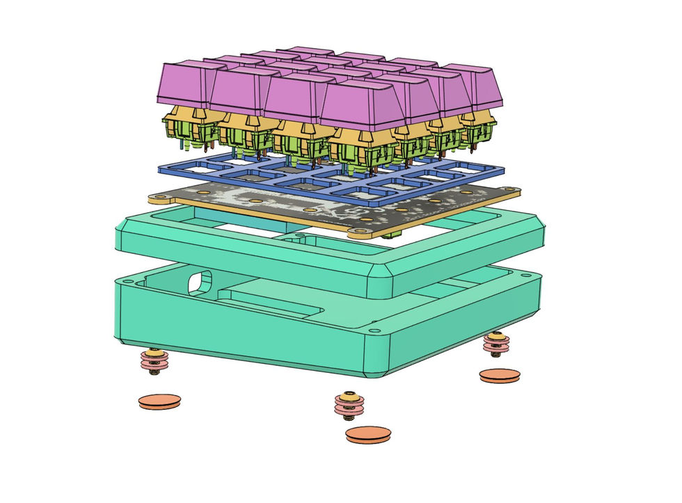
The original design inspiration came from this case. From there I modeled a fresh take which was designed for milling and with details to my tooth. We discussed different materials, from aluminum and steel to composites (fiber resin products like G-10). Aluminum was chosen for the initial run as it's cheap, easy to machine, and I had a in for some free anodizing.
Keeping things simple, I kept with a two piece clamshell, along with a printed PCB plate. The plate is bolted into the lower half of the case. The top plate is located with two pins, and fastened with two rare earth magnets. I used some nylon washers to isolate the PCB from the case and some rubber feet to keep things in place. McMaster to the rescue again. Don't forget the gamer #s engraved on the bottom.
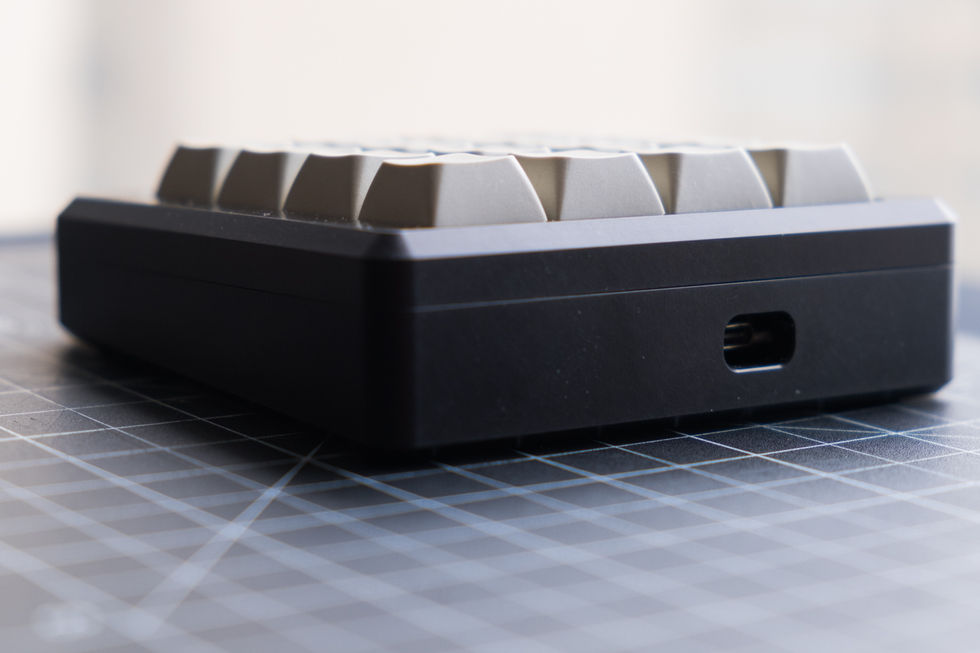
Manufacture: This was fairly straight forward. Two milled plates. The only tricky part was a non-parallel surface that gives the case a angle. I 3d printed a parallel to hold the part for Op2 as well as provide a pickup location for X (image below). My other concern was the pin alignment and fit. This didn't turn out to be an issue. A tight sliding fit, with the hole locations spaced correctly.
After milling, I used a scotchbrite pad on an orbital sander to give the faces a matte surface before sending out to plating. Off to Paterson, NJ they went for a dip. I was very pleased with the matte finish upon their return.
The final part was soldering the components to the board. This was fairly time consuming, and finicky. There were 16 LEDs soldered below each key for that sweet sweet RGB glow. The pads are miniscule and the LEDs sensitive to temperature. After cooking a few, I found the rhythm and the rest was history. Then came the diodes, switch, and microcontroller.
I won't go into the rest of the details with firmware and downstream configuration. There is plenty of documentation online for those wanting to jump in. QMK is a super valuable resource.
Conclusion: This was an enjoyable rapid prototyping project. A few weeks and we had a fully actualized and finished product.
I used the keypad for a few months along with a 60% keyboard primarily as a numpad, but also with function switches that activated different levels of key binds. Things like volume up/down, mute, play/pause were nice to have. I think the real value would be to program for certain programs.


